PRODUCT CENTER
MX8604G field type optical workstation
2022-06-09

Product Name: MX8604G Field Optical Workstation
The WR-8604G and WR-7504G series outdoor optical workstations are our company's advanced experience in successfully developing fiber optic transmission equipment for cable TV HFC networks over the years, specifically designed for bidirectional urban broadband networks with HFC structures.
MX-8604G, MX-7504G series field type optical workstations
1、 Product Overview
The MX-8604G and MX-7504G series field type optical workstations are our company's advanced experience in successfully developing fiber optic transmission equipment for cable TV HFC networks over the years, specifically designed for bidirectional urban broadband networks with HFC structures;
The design of this product fully considers the network topology of FTS (Fiber to Service Community), the engineering and technical challenges of collecting noise in the CATV bidirectional network return channel, and the high reliability network security transmission requirements of modern CATV services; Repeatedly optimized and improved the internal circuit structure;
Equipped with a well-established status monitoring circuit and a network management system compatible with HMS standards, this product can achieve remote network management monitoring of equipment through a network management responder, making it the preferred product for building high-quality bidirectional HFC urban broadband networks;
MX-8604G-P model imitates Philippe diamond structure, S-type imitates Atlanta G940 system structure, and internal configuration is currently top-notch (including indicators)
2、 Performance characteristics
The optical receiving part adopts the top international high sensitivity photodetectors; Low noise DFB laser is used for the transmission part of the feedback light, and the front stage of the RF amplification circuit adopts an imported top-level low-noise push-pull amplification module. The output stage adopts an imported top-level high-power gallium arsenide module (which can also be changed according to user requirements);
The fully modular design of the building blocks allows for the configuration of up to two optical receiving modules (S-type), two backhaul optical transmitting modules (S-type), and two power modules (S-type), effectively improving the reliability and safety of the system;
Two light receiving modules, which can be set to automatic or manual switching as needed; The hot backup module of the switching power supply automatically switches online (S-type);
Plug in duplex filter, plug-in fixed equalizer, fixed attenuator, scientific and reasonable online detection port, making engineering debugging more convenient;
All four output ports can output 108 dB μ The high-level signal of V is independently amplified by a power multiplier module in each channel, and the output level and output slope of each channel are independently adjustable; Directly drive around 100 end users (S-type) without downstream delay or user delay;
Equipped with a well-established status monitoring circuit and a network management system compatible with HMS standards, remote network management monitoring of equipment can be easily achieved by installing a network management responder, effectively improving network security and reliability.
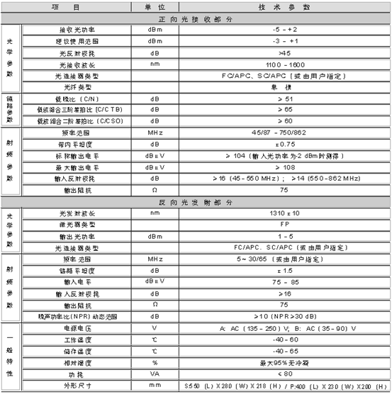
技术参数
Special note: The technical parameters of the equipment provided in this manual are based on the testing methods specified in GY/T 194-2003 "Technical Requirements and Measurement Methods for Cable TV System Optical Workstations", and are measured under the following testing conditions.
Test conditions: 1. Downlink optical reception part: Composed of a test link with a 10km standard fiber optic, optical passive attenuator, and standard optical transmitter. Under specified link loss conditions, 59 PAL-D analog TV channel signals are configured in the frequency range of 47 MHz to 550 MHz. Digital modulation signals are transmitted in the frequency range of 550 MHz to 862 MHz, and the level of the digital modulation signal (within the 8 MHz bandwidth) is 10 dB lower than the carrier level of the analog signal; The input optical power of the optical workstation is -1dBm, and the RF output level is 104 dB μ V. Measure the carrier combination third-order beat ratio (C/CTB), carrier combination second-order beat ratio (C/CSO), and carrier to noise ratio (C/N) when using a 9dB output slant.
2. Uplink optical transmission part: The dynamic range of link flatness and noise power ratio is a link indicator composed of uplink optical transmitter and uplink optical receiver.
Friendly reminder: In order to improve the nonlinear performance of cable transmission systems below the optical contact point, it is recommended to set the RF signal to a tilted output of 9-12dB in practical engineering applications.
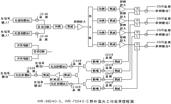
4、 Principle Block Diagram

五、可选选件
选件1:网管模块
选件2:网管应答器
选件3:光接收备份模块
选件4:回传光发射模块(FP激光器)
选件5:开关电源热备份模块
六、订购指南
本设备出厂默认配置为双向预留配置(一个光接收模块和一个开关电源模块);客户如需配置其它选件时,请在订货时
说明,并请说明双向通道的上、下行分割频率。
24-hour service hotline
Email:
mingxin8188@126.com
Address:East side of Guoshui Road, Shatou Town, Guangling District, Yangzhou City, Jiangsu Province

【 Wechat 】
Copyright© 2022 Mingxin Intelligent Optics (Jiangsu) Co., Ltd
